 AtariVideoMusic.net
Inside the C-240
No CPU. No software. Just op-amps, logic, and an RF modulator — a music visualizer built entirely from 1976 analog and small-scale digital parts.
Specifications
| Model | Atari Video Music, Model C-240 |
|---|---|
| Audio input | Left/right RCA line-level jacks from a stereo amplifier's tape/aux outputs |
| Video output | RF-modulated NTSC on VHF channel 3 or 4 (switchable) |
| TV connection | Adhesive-backed antenna switch box with 75-ohm pass-through F connector — antenna/cable stays connected |
| Power | AC mains; internal supply rails of ±12 V and +5 V |
| Key ICs | LM324 quad op-amps (audio path), CD4013 dual flip-flops and CD4011 NAND gates (counters/logic) |
| Cabinet | Brushed aluminum faceplate, particle-board sides with walnut veneer |
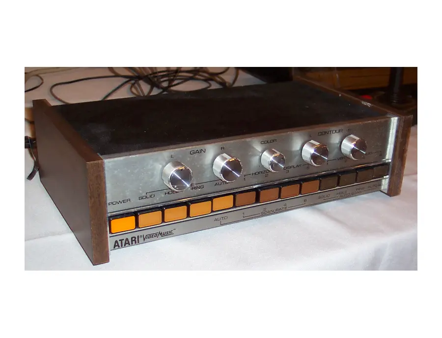
| Controls | Power switch, 5 potentiometers, 12 push-buttons |
Front-Panel Controls
| GAIN L / GAIN R | Input sensitivity per channel — directly controls the size of each diamond. Too high causes flicker; too low and the pattern collapses. |
|---|---|
| COLOR | Sweeps the chroma system from solid single hues to continuously cycling rainbow effects. |
| CONTOUR L / CONTOUR R | Shapes each channel's pattern from soft, organic curves to sharp geometric edges. |
| SHAPE buttons | Solid (filled), Hole (one shape subtracted from the other), Ring (outlines only), and Auto (random cycling). |
| HORIZONTAL / VERTICAL | Multiply the image into arrays — 1 to 8 repetitions in rows or columns. |
| AUTO ALL | Hands most settings to the machine, which cycles them pseudo-randomly, driven by the audio itself. |
Signal Chain
The architecture flows left to right across the board, exactly as described in the patent:
- Power supply: a linear supply producing ±12 V for the analog stages and +5 V for the logic. Its electrolytic capacitors are the number-one failure point today — see the Restoration Center.
- Vertical/horizontal counters: CD4013 flip-flops and CD4011 gates generate scan-locked timing and the array multiplication.
- Audio path: LM324 op-amps handle amplification, energy detection, and contour shaping.
- Shape logic: discrete gates implement the OR / XOR / delay combinations that make Solid, Hole, and Ring modes.
Full Schematic
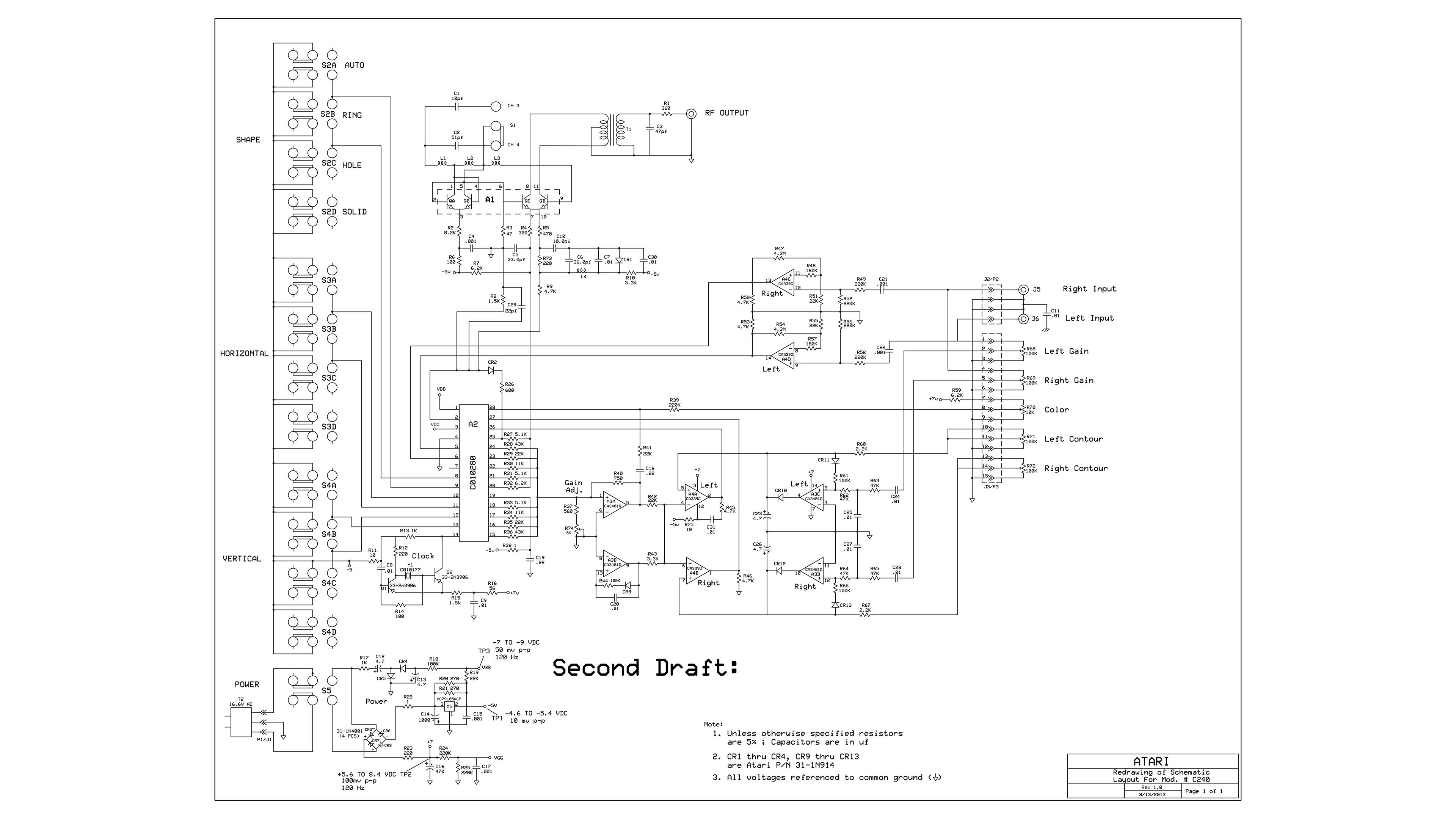
The complete C-240 schematic, redrawn for legibility. Click to open at full resolution — it's large enough to trace individual nets.
Shared DNA with the Atari 2600
Robert J. Brown was working on the Atari VCS (2600) at the same time as the Video Music, and it shows: both machines generate NTSC video with counter-driven timing chains and deliver it through a channel 3/4 RF modulator to unmodified televisions. The Video Music is, in a sense, a sibling of the most famous game console ever made — one that traded the CPU and cartridge slot for a pair of RCA jacks and a room full of op-amps.